Before attempting to install cts read the ct installation safety page. The only difference is that it is larger.
Be aware that these are general diagrams using standard test switches which may not match some utility standards in their configuration and are for reference only.
You can find out more Diagram below
Ct meter wiring diagram. Here it is with comments about the form 9s meter wiring diagram below. 6s wiring diagram 4 wire wye 3 ph 4 wire 2 pt 3 ct glems would like to thank and acknowledge the use of the following meter connection diagrams from dr. One of the questions that i often get is about how to wire a form 9s meter.
With and without cts and pts for wye delta and network circuits. For the form 4s meter wiring diagram lets start at the bottom. Ct installation and wiring explained by continental control systems.
Ammeter wiring which is only for low load and in this article you will learn that how to wire ammeter for high load or high ampere testing. Unused ct inputs could possibly pickup electrical noise so it is a good practice to short out. Meter wiring diagrams for low voltage meter stations for in whangarei and kaipara.
We supply these meters on the assumption that they will be installed by a qualified electrician familiar with the installation of metering equipment ensure all current transformers are installed as per wiringdiagram which can also be. How to wire a digital amp meter with current transformer. A complete guide of current transformer installation and wiring connection with ammeters.
Since i get this question so often i thought i would put up a form 9s meter wiring diagram. In this post i am sharing with you a diagram in which i wired an ammeter with current transformer which is well know with his short name ct coil. How to wire an digital ammeter volt and hz meter with ct and supply.
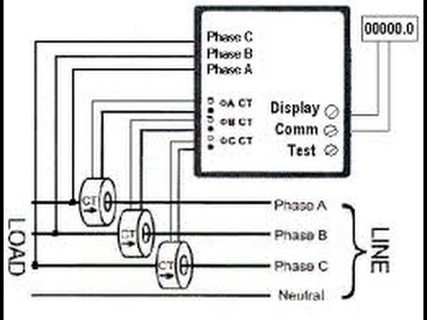
Make note that this is the same type of service that you find on most homes. Includes single phase 2 phase supply 3 phase supply multiple installations distributed generationalternative energy and typical equipment dimensions. In the above ct wiring diagram i common a wire of all ct s my means that i connect ct one connection with one another.
We have two phase wires and a neutral. Notice that we are going to be metering a single phase three wire service. It will be easier to connect the wires to the terminal block if the block is first plugged into the meter.
Showing wiring from a current transformer in a cabinet to the test switch and to the meter. One of the most requested items of information that we receive is for wiring diagrams for the meters we sell. Ct current transformer wiring connections for commercial form 9s electric meter installation.
Form 4s meter wiring diagram. This page contains circuit type and wiring diagrams for all the form s of meters sockets and pans. Current transformer wiring diagram instructions note.


0 comments:
Post a Comment